
The rectangular waveguides on Micro Harmonics isolator flanges are canted at a small angle ranging from 7° to 11° as indicated in Figure 1 (b). The tilted waveguide can be a little unsettling to look at. However, there is no need for concern because the impact of the discontinuity caused by the tilted waveguide has been accounted for and is part of the isolator design. The waveguide angle and the corner radii are precisely controlled.
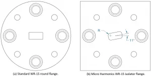 |
| Figure 1 – WR-15 waveguide flanges. (a) standard flange, and (b) typical flange used in a Micro Harmonics isolator. |
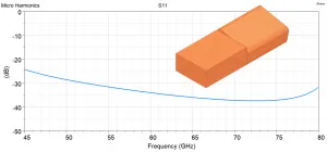 |
| Figure 2 – HFSS simulation data showing the reflections at the interface of the Micro Harmonics WR-15 isolator flange attached to a standard flange. The HFSS model is shown in the inset. |
Micro Harmonics provides measured RF test data with every isolator that we sell. The RF data is measured on a vector network analyzer with a pair of mm-wave frequency extenders. The frequency extenders have standard waveguide flanges like the one shown in Figure 1 (a). The frequency extenders are connected to the Micro Harmonics isolator flanges like the one shown in Figure 1 (b). The measured RF data therefore include the effects of the discontinuities at both mating surfaces.
There are small reflections at the interface between the tilted waveguide on our isolator flange and the waveguide on a standard waveguide flange. But the reflections are much smaller than you might think. These reflections have been accounted for in the design. In fact, the isolators require this discontinuity for optimal performance. Figure 2 shows the results of an HFSS simulation of the discontinuity of the Micro Harmonics WR-15 isolator flange connected to a standard WR-15 waveguide flange. The port reflections are less than -28 dB across the standard WR-15 band 50-75 GHz and less than -24 dB across the extended band from 45-80 GHz.
Why the Tilted Waveguide? – In a Faraday rotation isolator, the signal polarity is rotated by 45° as it passes through a ferrite rod. In traditional style Faraday rotation isolators, extruded waveguides with a smooth twist are used to realign the waveguides. In contrast, we use a pair of stepped waveguide twists on either side of the ferrite rod to realign the waveguide flanges. The stepped twists are much shorter, producing a much more compact isolator. In some respects, the stepped twists are not as aesthetically pleasing as the extruded twist, but the RF results are very good.
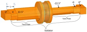 |
| Figure 3 – HFSS model of a Faraday rotation isolator. L and are designed to provide minimal reflections at the isolator ports. |
An HFSS model of a Faraday rotation isolator is shown in Figure 3. The cylindrical part at the center is the location of the ferrite rod where the Faraday rotation occurs. The waveguides on either side of the Faraday rotator are canted at +22.5° and -22.5°. L and θ are designed to provide minimal reflections at the isolator ports.
The two waveguides forming the “twist plate” are machined from a single metal plate using a CNC milling machine. The waveguides are formed with plunge cuts which is why the waveguide corners are rounded. The corner radii are tightly controlled.
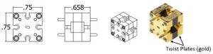 |
| Figure 4 – Outer dimensions of a Micro Harmonics WR-10 isolator model FR100M2. The 0.658 inch length is not arbitrary but rather is chosen to obtain minimal port reflections. |
We have experimented with smaller waveguide angles (θ) at the flange. Angles down to 7° work quite well. Many of our latest isolator designs employ the smaller angle. However, the overall performance of the isolator is not improved. The smaller angle is only used for aesthetic purposes.
Since the lengths of the ferrite rods and the twist waveguides are constrained, our isolators often have outer flange-to-flange dimensions that seem arbitrary. For instance, the flange-to-flange dimension of our WR-10 isolator model FR100M2 is 0.658 inches as shown in Figure 4. The location of the flange, the angle of the waveguide, and the corner radii in our waveguides are all part of the overall isolator design. These parts are precision machined to exacting standards. The tilted waveguides on our flanges may look odd, but they achieve very good RF performance and yield a very compact and low loss isolator.