
Voltage variable attenuators (VVA) find wide application in many microwave and millimeter-wave systems. At frequencies above 50 GHz, most VVA’s are either based on PIN diodes or resistive vanes with motor driven mechanical actuators. Both technologies cover full rectangular waveguide bands (40% fractional bandwidths). PIN attenuators are available up to the WR-10 band (75-110 GHz) with 20 dB dynamic range, 3 dB insertion loss, and 100 mW power ratings. Perhaps the primary appeal of the PIN attenuators is fast switching speeds near 100 ns. On the downside, they are sensitive to ESD damage and in some cases may generate low level noise and harmonic content.
Electronically tunable resistive vane attenuators are large, heavy, and slow compared to PIN devices. But they have a much flatter frequency response and significantly higher dynamic range. The resistive vane attenuators are useful in lab environments but are unsuitable for many fielded systems. They employ calibrated control circuits and motor driven actuators to precisely position a resistive vane within a waveguide. They are available up to the WR-2.2 band 330-500 GHz. In the WR-10 band they have 3 dB insertion loss, 60 dB dynamic range, two second switching speed, and 2 W maximum power rating.
Micro Harmonics is developing a third technology that uses a Faraday rotator to rotate the RF signal polarity into a fixed resistive layer embedded in a ceramic cone. This is similar to the resistive vane technology but eliminates the mechanical motion of the vane. The new Faraday Rotation Attenuators (FRA) have some unique characteristics that make them attractive options for mm-wave applications.
The FRA technology is passive which makes it insensitive to ESD damage. FRAs have characteristics such as flat response and high dynamic range that are much better than the PIN attenuators but not quite as good as the resistive vane devices. There are no moving parts in the FRA. The dynamic range of the MHC WR-10 FRA is 35 dB. However, a dynamic range up to 50 dB may be possible through refinements to the design. The FRA is lightweight and compact like the PIN attenuator. The FRA can be scaled to at least 330 GHz, well above the 110 GHz limit for commercially available PIN attenuators.
CVD diamond discs are used in the FRAs to channel heat away from the ferrite rods. The CW power rating for the WR-10 FRA is more than 2 W which is comparable to some resistive vane attenuators and significantly higher than the 100 mW rating for the PIN attenuators. Measured port reflections for the FRA are typically less than -17 dB. This compares favorably to the ‑10 dB level reflections in the PIN diode attenuators. The FRA switching speed is 10 ms. This is about two orders of magnitude faster than the resistive vane and five orders of magnitude slower than the PIN devices. And finally, the insertion loss of the WR-10 FRA is 1 dB which is less than the 3 dB insertion loss of the PIN diode and resistive vane attenuators.
The new attenuator is now available from Micro Harmonics in the WR-10 band (75-110 GHz). A WR-6.5 model covering 110-170 GHz will become available in August 2023. Models in other bands will follow. Please check our website periodically for updates.
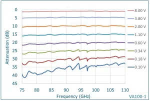
Our attenuator is configured so that maximum attenuation is achieved at 0 V bias. Measured data from our WR-10 attenuator is shown below. The dynamic range is more than 35 dB. The attenuator uses diamond heatsink technology and has a power rating in WR-10 of 2.3 W CW. Switching speed is 10 ms. PIN diode attenuators are faster, but our attenuator has a flatter response, higher power handling, and higher dynamic range. And it does not produce any intermodulation distortion products (none that we have been able to detect).
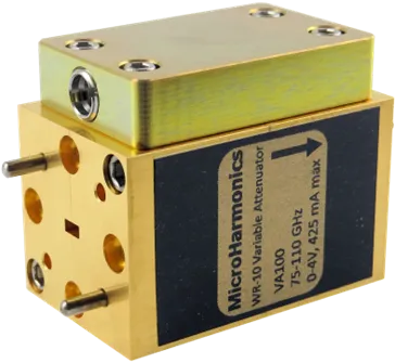 |
| WR-10 attenuator |
Our WR-10 attenuator is shown to the left. The attenuator is lightweight and compact with the main body measuring 0.75 x 0.75 x 1.2 inch (19 x 19 x 30 mm). The small size makes the attenuator very easy to fit into millimeter-wave systems. A DC control voltage is applied through an SMP (M) connector.